IQ Signals
Most signal processing for modems is done with a complex baseband representation of signals referred to as an "IQ signal". This naming convention is making reference to the "in-phase" and "quadrature-phase" decomposition of a sinusoid, which can be assumed to be a near orthogonal decomposition when the narrowband signal model is assumed. This orthogonality allows for a clever trick where information can be transmitted on the two components of the signal independently for an increase in data throughput.
Narrowband Signal Model
An RF signal in all communications contexts takes the form of a time-varying amplitude and phase modulating some carrier frequency .
A narrowband signal model makes the assumption that the amplitude and phase vary slowly relative to the carrier frequency . The model is called "narrowband" because when is a constant (as it appears to be on a short enough timescale if we assume it only changes slowly) then we are left with a pure sinusoidal signal whose bandwidth is 0. If we allow that is not constant, but merely slow, then we see our bandwidth increase from 0 to something narrow. Hence, the narrowband signal model.
Orthogonal Decomposition
In trigonometry one of the angle sum identities is:
If we apply this identity to our RF signal referenced above then we would end up with the following at any particular time :
We observe from this decomposed form of the RF signal that from the first component of the decomposition and the from the second component are exactly radians out of phase with each other.
Then there exist many discrete points in time such that and so the first component vanishes completely. Simultaneously, at these exact points in time the term from the second component is maximized.
Likewise, we see that at times the opposite holds true and so that the second term vanishes, while the of the first term is maximized.
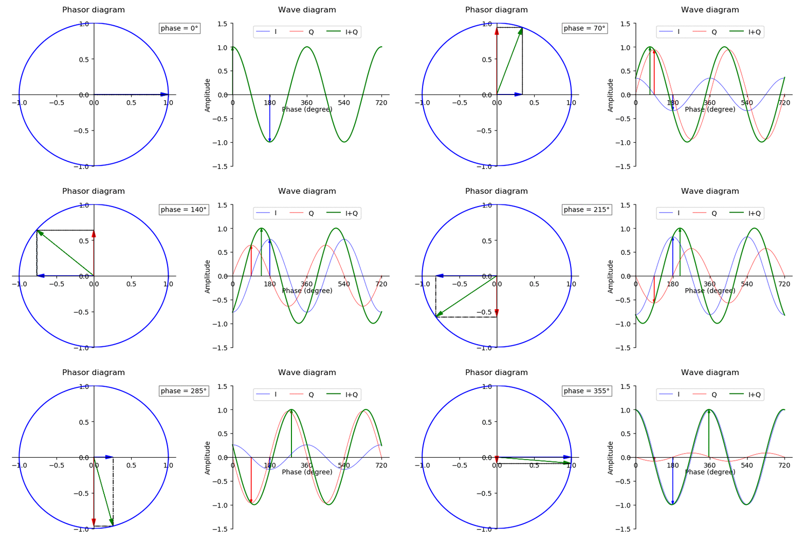
A fantastic illustration of this decomposition in action at the very fast/short timescale can be seen in this graphic from the Wikipedia article on this subject:

Due to this behavior when and are taken as constants we see that the "in-phase" and "quadrature-phase" (first and second components) are orthogonal functions. When we allow for slowly time varying and the orthogonality is no longer exact, but it is approximately maintained.
On a long enough timescale and are allowed to vary in our narrowband signal model, and they can be adjusted so that if the signal (and a radian phase delayed copy) is carefully sampled at some symbol rate we will observe the I and Q values of the signal, which correspond to the amplitude of the in-phase and quadrature-phase components. Through the decomposition we note that adjusting and sampling the "IQ" values is equivalent to the adjusting and sampling and of the signal. IQ values are preferred because they can be mapped to the complex plane (as seen above) and allow for more standard Euclidean geometry and mathematical approaches.
Exploit Orthogonality
Given this access to IQ values which map to a complex plane, we can more information per IQ symbol than if we merely adjusted the amplitude of the RF signal. We have access to a whole other dimension of channel capacity in !
If we ignore for a moment how these symbol timings referred to above are decided, we note that a given IQ value pair maps to a point on the complex plane. If we decided that we would use only two distinct points then we would be able to transmit 1 bit of information per symbol, and we'd optimally end up with a classic BPSK constellation map:
If instead we decide to put the Q values to work, we could choose 4 points allowing us to transmit 2 bits of information per symbol and arrive at a QPSK modulated signal:
This game can be continued for quite some time, although eventually practical limitations arising from noise in the system limit the ability of the receiver to be able to tell points apart which are too close together:
Although somewhat difficult to visualize, do try to imagine the above animation but with the blue and red (I and Q) arrows extending in and out towards a particular point in these constellation maps repeatedly. Now when the symbol changes (slowly relative to the oscillations of the blue and red arrows) they begin pointing to a new point in the diagram. The time domain sinusoids traced by the two would shift in amplitude in phase slowly as the symbols are adjusted. If you can manage it you'll have a valuable mental image of what is happening in a communications signal, and a lot more insight into what modems are trying to achieve.
